The relative focus and the effective measurement angles are affected by the curvature.
Curved & Freeform Display Metrology
Even though flat screens are the most commonly used displays, concave-shaped monitors and freeform displays are also well-established in the automotive sector. While the measurement tasks and devices are hardly affected by the shape of the screen, an adaptation of the measurement methods is required if the screen is locally curved. Thus, LMK, LMK software, and lenses can be used for both types of displays. However, the alignment process can become more complex than with flat screens. This is true for uniformity measurements and conoscopic measurements. In recent years, TechnoTeam has gained much experience with this issue. The following table summarizes the required changes between flat panel displays and curved/freeform display testing.
Required changes between flat panel displays and curved/freeform display testing
| Flat panels | Curved*/free-form | |
|---|---|---|
| Alignment field angle | DFF BlackMURA field angle test | Conoscopic measurements might be required to check field angle |
| Defocus and Moiré | DFF reproducible defocus | Moiré/focus more likely to change across the display |
| Uniformity and BlackMURA measurements | Standard DFF alignment procedure | Complex alignment procedure, optionally complex field angle correction required*** |
| Sticking image | Standard DFF alignment procedure | Standard DFF alignment procedure |
| Sparkle | Standard procedure | Standard procedure** |
| Resolution measurements | Standard procedure | Standard procedure** |
| Reflection measurements | Standard procedure | Standard procedure** |
| Conoscopic contrast measurements | Standard procedure | Complex alignment procedure |
| APR and image stitching | Standard procedure | Standard procedure |
| Defect pixel analysis | Standard procedure | See defocus and Moiré |
| DeMURA | Standard procedure | See Defocus and Moiré |
* In this table, curved refers to a display with a local radius of curvature of 800 mm or more.
** Assuming that the display curvature is locally negligible.
*** Contact TechnoTeam if you require more information on your specific project.
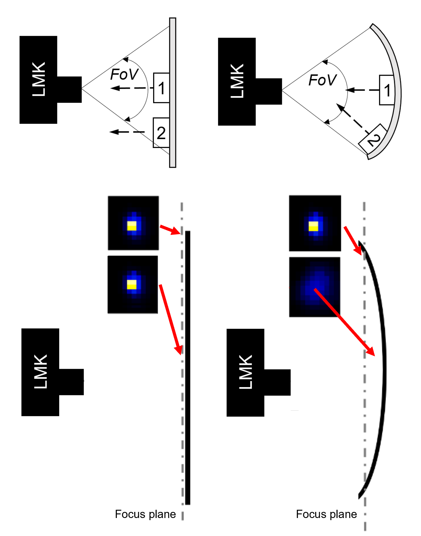
Field angle alignment for curved displays
The effective measurement field angle determines the impact of the display angular characteristic on the spatial uniformity measurement. The problem is shown in the top part of the figure. The angle between lens and display depends on the specific display pixel. While for a flat panel, a large measurement distance limits this effect, this is not necessarily true for curved displays. In contrast to flat panels, the surface normal of the display changes across the field of view. For a circular curvature, the ideal measurement point would be the center of curvature (measurement distance = radius of curvature). However, as the radius of curvature can usually vary locally or between the vertical and horizontal position, an ideal measurement position does not exist, and this aspect becomes very complex.
An individual analysis based on the measurement position, shape, and size of the curved display and its viewing angle characteristics (LMK conoscopic contrast measurement) is required to check the impact of the field angle. Based on this analysis, specific correction files can be derived to correct the field angle effect for curved displays.
Defocus and Moiré for curved displays
The focus plane of an LMK lens is usually designed to be in a specific plane. Thus, a curved shape can change the relative focus quality and sharpness, which impacts the results of DeMURA and defect-pixel analysis as well as the Moiré and defocus procedure. Besides the possibility of designing the LMK lens to realize a higher depth of focus, our APR image stitching can be used to minimize the effect. A reproducible defocus is possible for curved and flat panels.
Conoscopic contrast for curved displays
The measurement distance of the conoscope should be selected to minimize the measurement area. For the conoscopes of TechnoTeam, this corresponds to a measurement distance of a few millimeters. That way, the local radius of curvature can be neglected. Furthermore, depending on the measurement location on the curved surface, the perpendicular alignment, i.e., aligning the optical axis of the conoscope with the local surface normal, is required. TechnoTeam offers specific alignment tools and the LMK Position system to simplify this process and to ensure reproducible and reliable angular luminance, color, and contrast measurements on any display shape.
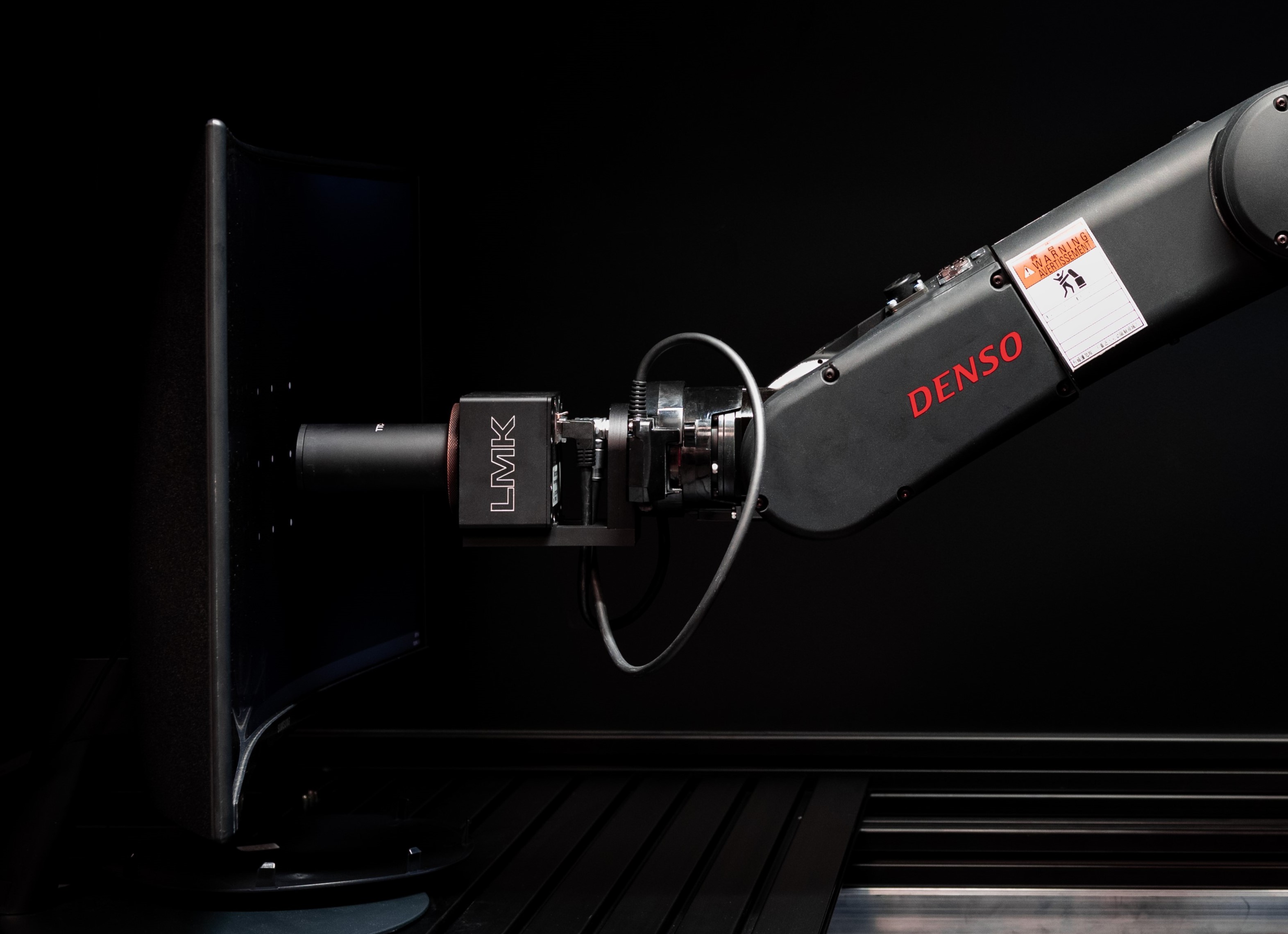
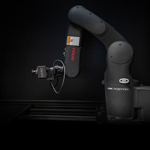
LMK Position is used to align a conoscope on a curved display.
Our Solution
The LMK 6 and LMK 6 color camera, software, and lenses can all be used for flat and curved display metrology. However, the alignment process and geometrical considerations can be more complex for curved displays than for standard flat displays. This is especially true for uniformity measurements according to BlackMURA and conoscopic measurements. In recent years, we have gained a lot of experience in this area and can support our customers when measuring complex shapes. We also offer a vision-based robotic system, the LMK Position, which massively simplifies the alignment process and offers full flexibility regardless of the display shape and curvature. Please click on the links below to learn more about specific measurement solutions.
RELEVANT PRODUCTS
RELEVANT PUBLICATIONS
Fast and Accurate Acquisition of Pixel-Level Luminance DeMURA-Data for Curved and Freeform Displays
International Meeting on Information Display (IMID 2022)
Modern single-pixel emitter displays such as OLED, MicroLEDs and LEDs suffer from production-related non-uniformity. The luminance and chromaticity can vary locally from pixel to pixel, resulting in a high-frequency non-uniformity and globally leading to a low-frequency non-uniformity. In order to correct these effects, luminance data of individual subpixels need to be measured. However, this is a very challenging and time-consuming task, especially for modern high-resolution displays.
To ensure a correct pixel registration (assigning the luminance to the correct pixel) in state of the art methods, display pixels are partially switched off [Patent US9135851B2]. However, this reduces cycle time and changes the average pixel level, which can affect the results.
We present a method to overcome these issues, called Advanced Pixel Registration (APR). It is based on a specific registration pattern applied during a teach-in process. An example pattern is provided in Figure 1 (left). After this initial registration, DeMURA measurements can be performed with only one image capture per input signal. The same is true for following displays during EOL testing, as small misalignments, which occur in production control environments as slight shifts, inclinations or rotations of the DUT (see Figure 2) can be corrected automatically.
This contribution validates the APR method using a flat and free-form curved display with methods similar to [] Feng, X. (2019), 78-2: Measurement and Evaluation of Subpixel Brightness for Demura. SID Symposium Digest of Technical Papers, 50: 1122-1125.]. The results show that the APR method can significantly improve the efficiency of DeMURA processes required for high-quality LED, OLED and MicroLED displays, regardless of their shape.
Advanced Alignment and Metrology Concepts Using Photometric Robotics with Examples for Automotive Displays
International Conference on Display Technology (ICDT 2021)
The alignment quality and reproducibility in ILMD (Imaging Luminance Measurement Device) based display metrology has a great influence on the reproducibility of the obtained measurement data. In this context, this contribution outlines and introduces several advanced measurement and alignment concepts that can be performed with “photometric robotics”. The term describes machine vision performed with an ILMD supported by robotic movements.
Distinguished Paper: Short Distance Uniformity and BlackMURA Measurements
Journal of the Society for Information Display
The increasing display sizes and changing form factors of displays, including automotive displays, lead to impractical measurement distances for lateral uniformity measurements. This contribution suggests and exemplarily applies two alternative and combinable methods to allow lateral uniformity measurements at low distances and describes an adjusted BlackMURA compliant validation procedure. The proposed methods are validated with a high-quality display device and are compared to results using the standard long-distance measurement procedure.