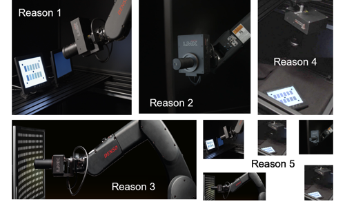
Reasons one to five: simple, fast and reproducible alignments
LMK Position: Robotic Display Metrology System
Alignment and measurement with 6-axis robot
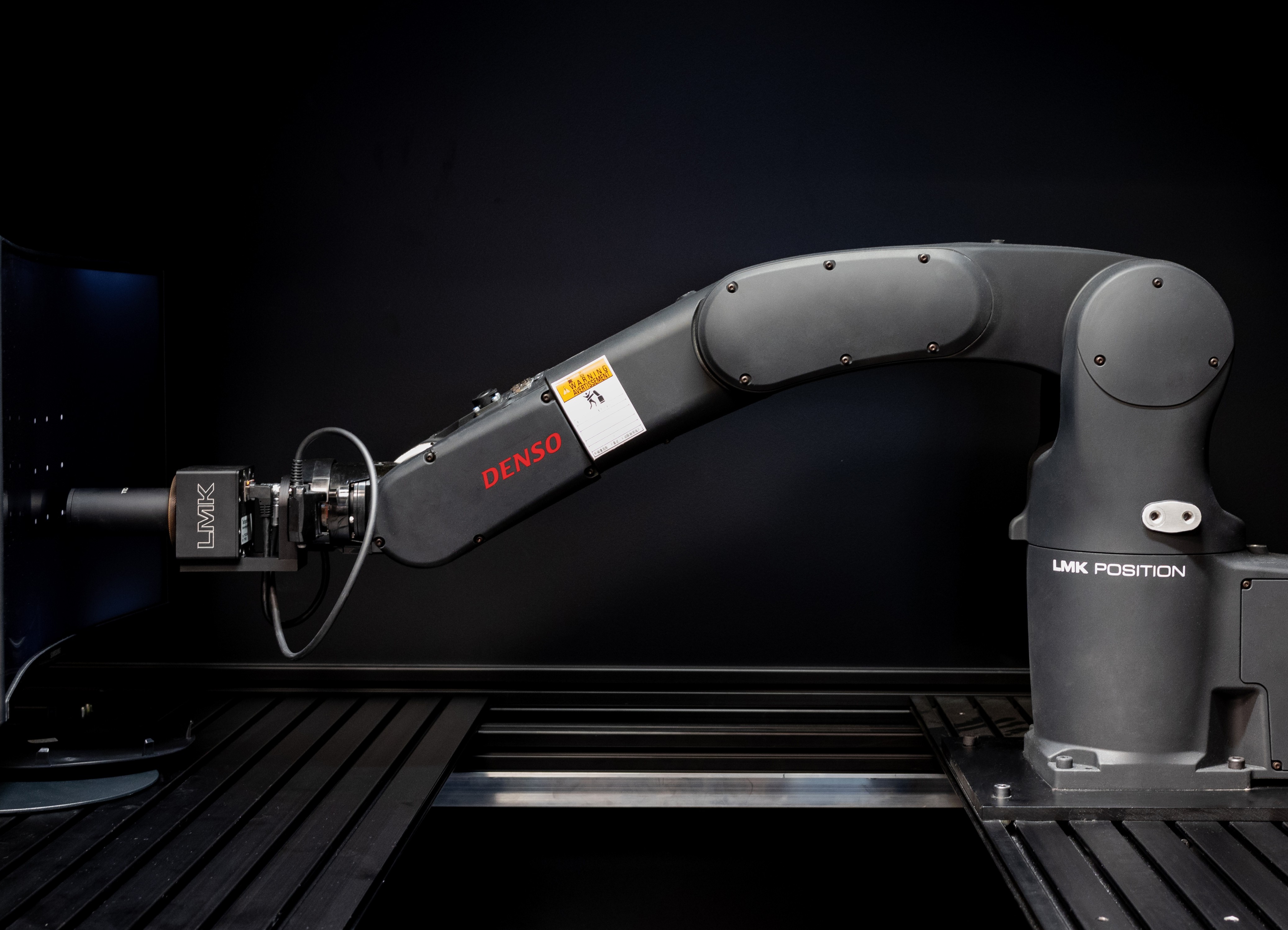
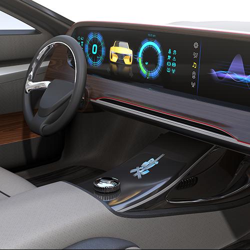
LMK Position is a robotic display metrology system that combines a high-resolution LMK luminance measurement camera (ILMD) with a 6-axis industrial robot. It delivers automated, precise and reproducible measurements on all types of displays — and is particularly well suited to automotive, curved and freeform display development, prototyping and small-series production.
The system simplifies and accelerates the entire measurement process:
- Automated alignment — time-saving, low-error, reproducible.
- Flexible measurement — in accordance with international specifications and standards (e.g. DFF, ICDM) and combinable with various measuring devices.
Thanks to intelligent image processing and proven calibration technologies, LMK Position is the ideal solution for research, development and small series production.
Top ten reasons for LMK Position
- Fast vertical alignment: Automated DFF BlackMURA alignment in just a few seconds
- Precise angular measurement: Fully automated and highly accurate goniometric measurements.
- Exact conoscopy: Automatic alignment of our conoscope on any curved display using 3D scan, including pixel structure avoidance.
- Unrestricted range of motion: 6-axis movement without restriction thanks to protected cable routing.
- Intelligent tripod: Multiple storable camera positions for consistent reproducibility.
- Easy handling: No need for complex, one-off fixtures — ideal for prototypes.
- More detail thanks to image fusion: Higher resolution thanks to image stitching — depending on the lens.
- Intelligent functions: Automatic focus, defocus, sparkle scan and virtual image distance measurement — even with manual or fixed-focus lenses.
- Multi-system compatibility: All alignment functions can also be used with the spectroradiometer specbos 1211 or specbos 2501.
- Modular and flexible: Luminance camera, spectroradiometer and robots can also be used individually — with temporary system dismantling.
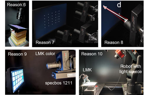
Reasons six to ten: cost-efficient and future-proof metrology improvements
Request more information now and arrange a demonstration
Lade Player...
Integration & Safety
TechnoTeam offers complete integration on site in the EU, South Korea and China. All relevant safety standards are met. Documents on the installation and scientific publications are available here.
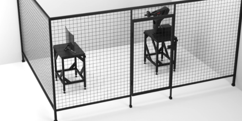
Example of a common integration of an LMK Position System
| Technical data | |
|---|---|
| Maximum arm reach | 875 mm |
| Number of axes | 6 |
| Encoders and motors | Absolute encoder; AC servomotors and brakes for all joints |
| Motion range | J1: ±170°; J2: +135° -100°; J3: +153° -136°; J4: ±270°; J5: ±120°; J6: ±360° |
| Position repeatability (at the center of the camera mounting) | ±0.03 mm |
| Weight with Aluminum-profile rack (incl. robot, LMK, controller, cables) | <150 kg |
| Aluminum-profile rack dimensions (L × W × H) | 780 × 780 × 950 mm (Robot installation height: 970 mm) |
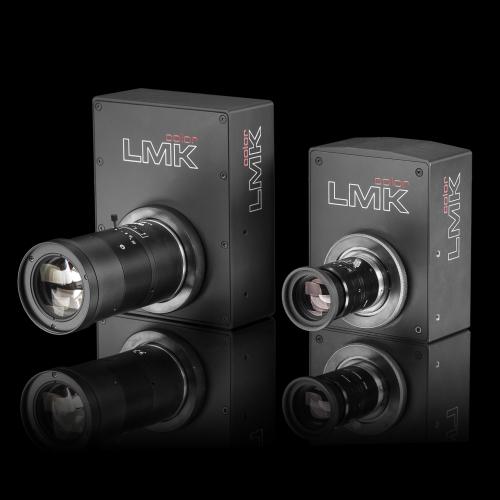
| Compatible cameras | LMK 6-5, LMK 6-12, LMK 6-30 |
| Installation environment of robot | Temperature: 0 to 40°C; Humidity: 20 to 90% RH; Vibration: 4.9 m/s² (0.5 G) |
| Optional equipment |
|
FAQ — LMK Position
Why combine an ILMD with a 6-axis robot — what does this replace?
Conventional ILMD-based display setups rely on manual alignment fixtures (jigs, holders, brackets) and on customised or specialised multi-axis goniophotometer mechanics to position the camera relative to the DUT. For each new prototype or each new measurement geometry the operator has to re-build or re-adjust the fixture — slow, error-prone and impractical for freeform / pillar-to-pillar displays.
Photometric robotics replaces both: the 6-axis kinematics delivers the angular freedom of a goniometer plus the translational freedom of an XYZ stage, and each measurement position is approached either through vision-based alignment — the ILMD live image drives the robot to the correct pose (BlackMURA pattern, conoscope alignment, sparkle scan, etc.) — or through deterministic recall of a stored pose. Both modes are reproducible independent of the operator and remove the need for one-off mechanical fixtures.
What does ±0.03 mm position repeatability mean in practice?
The ±0.03 mm figure refers to the mechanical pose repeatability at the camera mount — i.e. how precisely the bare robot returns to a stored joint configuration. In day-to-day display metrology this matters in two ways:
- Run-to-run consistency: when the same camera pose is recalled (e.g. for BlackMURA on a series of DUTs), the camera arrives at essentially the same position every time. This removes a major source of operator-dependent variation that variable setups suffer from.
- Effective alignment quality at the DUT: the final alignment seen by the measurement is not set by the robot alone — it is dominated by the vision-based fine alignment of the LMK (BlackMURA pattern, conoscope alignment, APR, etc.). The robot delivers a pose that is mechanically tight enough that the optical alignment converges quickly and reliably, on every DUT and in every setup.
Which cameras and measuring devices can be mounted on LMK Position?
Compatible LMK cameras: LMK 6-5, LMK 6-12 and LMK 6-30 (i.e. the current LMK 6 line). In addition, all alignment functions can also be used with the spectroradiometers specbos 1211 or specbos 2501-LAN. With LMK Position, the photometric-robotics alignment is performed with the LMK (or via a teach-in step), and the spectroradiometer then inherits the resulting pose for spectral measurements. The camera, spectrometer and robot are also separable for standalone use.
What is "automated DFF-BlackMURA alignment" — and what other alignment-related accelerations does it offer?
BlackMURA — the de-facto standard for low-frequency uniformity measurement of automotive displays — mandates a precise vertical (on-axis) alignment of the camera to the DUT.
LMK Position automates this alignment in a few seconds by using the live luminance image to drive the robot to the BlackMURA-compliant pose. The platform also automates the BlackMURA field-angle test that verifies whether the chosen measurement distance is acceptable for the current camera / lens / DUT combination — a check that is otherwise often skipped under time pressure, and that directly affects the validity of every downstream BlackMURA result.
How does LMK Position help with conoscopic measurements on curved displays?
Conoscopic measurements (viewing-angle luminance, colour, contrast) require the optical axis of the conoscope lens to be perpendicular to the local surface of the DUT. On a flat panel this is straightforward; on a curved display the local surface normal changes across the DUT, so each measurement point needs its own re-alignment.
This is where LMK Position is particularly valuable: the system performs a 3D scan of the DUT surface and then drives the conoscope automatically to the correct local pose for every measurement point — including pixel-structure avoidance so the small conoscope aperture is not placed on a sub-pixel gap. Multi-point angular characterisation across a curved display becomes practical, where it would previously require a manual re-alignment cycle for every single point.
What other measurement tasks does LMK Position automate?
Beyond BlackMURA and conoscopy, the robot platform automates the alignment-critical steps of several display-metrology workflows:
- Goniometric measurements with the imaging luminance camera — "Vantage Points": the robot drives the LMK through arbitrary pre-defined viewing positions (e.g. driver, co-driver, rear-seat) and captures angularly resolved luminance / colour data at each one. The same trajectories can optionally be executed with the specbos spectroradiometer mounted on the robot for spectrally resolved data at the same positions.
- Image stitching for ultra-wide / pillar-to-pillar displays (21:9, 32:9, 6:1 etc.): multiple captures are merged into one seamless luminance image via the Advanced Pixel Registration (APR) method.
- Display sparkle / anti-glare-layer evaluation: the automated distance focus scan locates the position of maximum sparkle visibility, which is used by us for reproducible sparkle measurements according to IEC 62977-3-9.
- Auto-focus / defocus and DFF-reproducible-defocus routines — also usable with manual or fixed-focus lenses.
LMK Position can also be combined with virtual image distance (VID) measurements using parallax — the robot precisely shifts the LMK between two defined positions, and the apparent shift of the displayed image is triangulated to derive the VID.
What is "photometric robotics" — is this a TechnoTeam term?
Photometric robotics is the concept of combining machine vision, photometry and industrial robotics in one platform: an Imaging Luminance Measurement Device (ILMD) drives the robot through the alignment, the robot positions the ILMD (or a spectroradiometer / conoscope), and the resulting measurement is geometrically referenced in the DUT coordinate system. The term was introduced and developed by TechnoTeam in several conference and peer-reviewed papers from 2021 onward, with LMK Position being the commercial implementation.
How accurate is LMK Position as a photometric goniometer?
Published figures from the peer-reviewed paper "Goniometric Measurements Using Photometric Robots With Imaging Luminance Measurement Devices (ILMDs)" for an LMK 6-30 (100 mm lens) on the LMK Position robot:
- Robot pose repeatability (after ≈ 90 min warm-up): max residual position error ≈ 0.01°.
- Goniometric scan accuracy (250 mm scan distance, 0° ≤ ϑ ≤ 60°, full 360° azimuth): typically 0.1°–0.2°, max 0.28° at ϑ = 60°.
- Position invariance: no measurable trend across five DUT positions inside a 300 mm goniobox — no "sweet spot" tuning required.
- Lens reattachment: no change within measurement uncertainty.
An optional absolute robot calibration reduces the maximum angular error to 0.04°–0.15° (mean ≈ 0.05°), but requires specialised tooling and recalibration after each maintenance event — recommended only when the application truly needs that level of absolute accuracy. For most display-metrology tasks the standard configuration is sufficient.
Which standards, OEM specifications and international guidelines does LMK Position support?
The system is designed to perform alignment and measurement according to international display-metrology specifications, in particular:
- DFF specifications (Deutsches Flachdisplay Forum) — including DFF BlackMURA, DFF Gamma, DFF Sticking Image, DFF OLED.
- ICDM / IDMS 1.3 chapter 3.8 (Information Display Measurements Standard, SID / ICDM).
- IEC 62977 family — e.g. IEC 62977-3-9 (sparkle)
Because LMK Position is a platform, it inherits the standard compliance of the LMK camera and the relevant add-on (BlackMURA, Conoscope, Reflection, Sparkle, Sticking Image) — and it adds the alignment automation required to make those measurements both reproducible and practical on modern, complex display shapes.
How does LMK Position compare to a classical goniometer?
Both system types have valid use cases — the right choice depends on the angular range, the DUT geometry and the level of automation the application needs.
Classical goniophotometers cover a wider angular range (up to ±180° in some configurations) and remain the reference choice when very wide measurement angles or the highest absolute precision are required. Accuracy, setup time and DUT-handling vary substantially by model and price class.
LMK Position covers inclination angles up to 60°–75° with full 360° azimuth — spanning the practically relevant viewing zones for both automotive and consumer displays. The automated, vision-based alignment workflow keeps initial alignment fast and largely independent of the operator, and the DUT can be placed anywhere within a ~300 mm × 300 mm × 300 mm goniobox: prototypes with non-standard holders, curved panels, pillar-to-pillar displays and loosely mounted modules can all be measured — situations that would typically require a custom DUT fixture on a classical system with a fixed rotational centre.
A methodical comparison of photometric-robotic and classical systems for display metrology is given in our peer-reviewed paper "Goniometric Measurements Using Photometric Robots With Imaging Luminance Measurement Devices (ILMDs)".
Is LMK Position more affordable than a customised multi-axis system?
Yes. LMK Position is built around a 6-axis industrial robot — a mass-produced commodity component — so the system is typically less expensive than the customised, high-precision multi-axis mechanics that would otherwise be required for the same alignment and goniometric tasks. Industrial 6-axis arms amortise their development across many industries, whereas customised measurement mechanics are essentially single-application builds. Concrete pricing depends on the chosen camera, lenses and options, so figures are quoted per project.
Two effects compound this on a total-cost-of-ownership basis: (1) the same platform serves BlackMURA alignment, conoscopy, image stitching and goniometric measurements — one instrument replacing several dedicated tools — and (2) the robot's freedom of movement is shared by two measurement instruments at once: the LMK captures luminance and colour at each Vantage Point while the specbos spectroradiometer simultaneously delivers spectral data at the same positions during a goniometric scan.
Is LMK Position suitable for production / EOL — or only for R&D?
Beyond R&D, LMK Position is also well suited to end-of-line (EOL) tests where movement is unavoidable — for example, when multiple measurement positions on the same DUT must be addressed within the cycle time, or when several DUT variants share the same EOL station and a fixed mechanical fixture is not practical. For very high-throughput EOL with a single DUT type and a single measurement geometry, a dedicated mechanical fixture can still be more cost-effective; LMK Position's strength is the mid-volume, high-mix segment plus multi-position EOL tasks.
Can LMK Position be controlled programmatically — which SDK languages are supported?
Every LMK Position system ships with a graphical user interface (GUI) and an SDK. The SDK can be called from all common programming languages — Python, MATLAB, C++ and LabVIEW. Code examples and the SDK documentation are available on request.
In which regions can the system be integrated, and what about CE / safety documentation?
Complete on-site integration is offered in the EU, South Korea and China, by TechnoTeam together with regional partners. The configured system meets all relevant safety standards. For installations in other regions, please contact TechnoTeam directly to discuss a suitable integration path.
Every EU installation is delivered with a project-specific CE declaration and a full documentation set tailored to the actual layout, additional safety devices and the customer's existing safety perimeter — this is the binding documentation for the delivered system. The downloadable Setup and Safety of LMK Position document is intended as an overview for early-stage planning; the equivalent regional documentation for installations in South Korea and China is provided through our local partners.
Can LMK Position be used for non-display measurement tasks?
Yes — but with a caveat. The two purely geometric strengths of the platform are not display-specific:
- Repeatable approach of stored poses — e.g. for any DUT that has to be measured at multiple, well-defined positions in space.
- Goniometric sweeps — moving the LMK (and optionally the specbos) through pre-defined viewing directions.
These work just as well for non-display DUTs (illuminated objects, control panels, lighting modules, etc.).
The caveat is that several of the automated alignment functions rely on test patterns that a display can generate naturally — the BlackMURA-style perpendicular-alignment routine, for example, assumes a test pattern can be shown on the DUT. For non-display DUTs these patterns have to be provided externally (printed targets, an array of illuminated LEDs, an auxiliary display in the measurement plane), which is feasible but adds setup effort. For pure pose-recall or goniometric use this caveat is small; for the full vision-guided workflow on non-display objects, the test-pattern setup should be discussed up front. First customer systems implementing such extensions are already in operation.
RELEVANT PRODUCTS AND APPLICATIONS
Publications
Goniometric Measurements Using Photometric Robots With Imaging Luminance Measurement Devices (ILMDs)
Journal of the Society for Information Display
When measuring display-specific parameters such as luminance, contrast, or color, which depend on the viewing angle, precise and reproducible positioning of the measuring system is essential for achieving reliable results. This study examines how photometric robots, which integrate imaging luminance measurement devices (ILMDs) with industrial robotic systems, can be used as goniophotometers for display and illuminated object measurement technology. Physical limitations are discussed, and the position accuracy and repeatability are analyzed. Recent advancements in this field are explored, including enhanced goniophotometric functions, spectroradiometer integration, absolute robot calibration methods, and specialized software innovations.
Advanced Alignment and Metrology Concepts Using Photometric Robotics with Examples for Automotive Displays
International Conference on Display Technology (ICDT 2021)
The alignment quality and reproducibility in ILMD (Imaging Luminance Measurement Device) based display metrology has a great influence on the reproducibility of the obtained measurement data. In this context, this contribution outlines and introduces several advanced measurement and alignment concepts that can be performed with “photometric robotics”. The term describes machine vision performed with an ILMD supported by robotic movements.
Precise Virtual Image Distance Measurements Using Imaging Luminance Measurement Devices with Type II Calibration
SID Vehicle Displays & Interfaces 2022
As head-up displays play an increasingly important role in modern vehicle cockpits, there is a growing demand for measurement procedures to characterize them. There are two general approaches to measuring virtual image distance, a parallax-based triangulation method and a focus-based technique. They can be performed using Imaging Luminance Measurement Devices with type II calibration, making them suitable for photometrical and geometrical measurements. This paper examines the advantages and drawbacks of both methods using mathematical models and measurement data.
Distinguished Paper: Short Distance Uniformity and BlackMURA Measurements
Journal of the Society for Information Display
The increasing display sizes and changing form factors of displays, including automotive displays, lead to impractical measurement distances for lateral uniformity measurements. This contribution suggests and exemplarily applies two alternative and combinable methods to allow lateral uniformity measurements at low distances and describes an adjusted BlackMURA compliant validation procedure. The proposed methods are validated with a high-quality display device and are compared to results using the standard long-distance measurement procedure.
Photometric Robotics for Fast and Precise Human-Centered Automotive Display Metrology
SID Vehicle Displays & Interfaces 2021
The increasing complexity of automotive displays in terms of design, shape, and degree of integration leads to an increasing complexity of setup and alignment procedures. In this context, the effort required to ensure reproducible measurement results, e.g. for prototypes or in research and development is also increasing rapidly. We introduce the concept of photometric robotics which combines machine vision, photometry, and robotic to solve these challenges.
- Type:
- Package
- Applications:
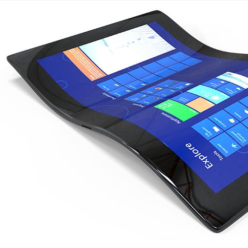
- Automotive Display
- Measurands:
- Color measurement Light measurement
- Tasks:
- Automation & Industry Development & Industry Science & Research