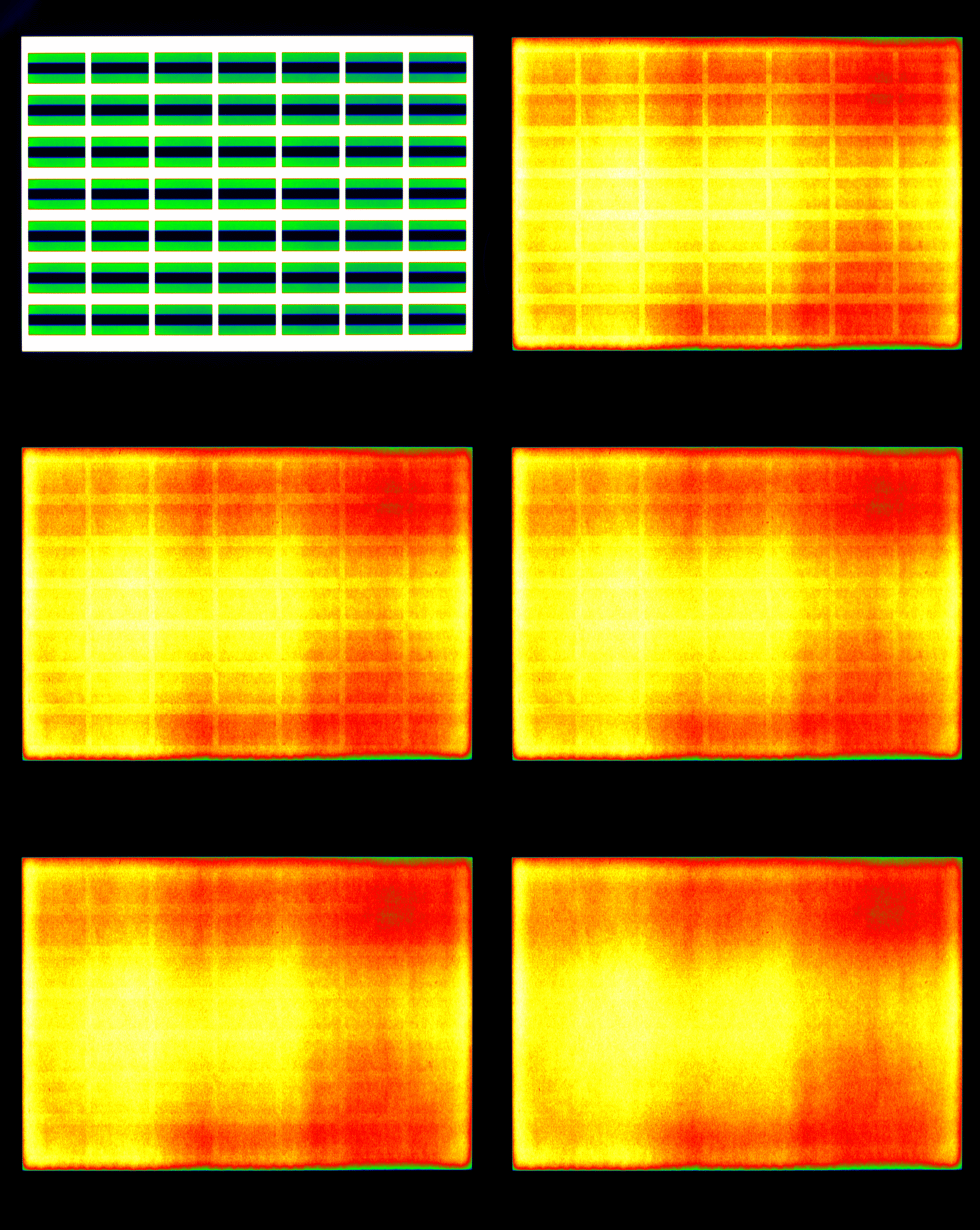
Luminance images of the evaluation period that show the vanishing image sticking phenomenon
Advanced image sticking measurements
Application Note – Advanced image sticking measurements
This page shows a summary of the application note. Topic of the document is the measurement of image sticking on displays and the most important aspects that have to be considered during a measurement. These concepts are general and thus independent on any specific evaluation method.
What is image sticking?
Static image content is typical for specific displays, for instance, in the public sector at airports and train stations (traveling information), on touch screens (app symbols), or even video gaming in consumer applications or smartphone applications. If the image is updated, a ghost image of the previously static content may remain temporarily or permanently visible. This phenomenon is called image sticking, residual image, latent image, image retention, or burn-in. This application note helps to understand important aspects of the image sticking measurements. It describes the options and advantages within the TechnoTeam evaluation procedures using either an LMK5 or LMK6 and the LabSoft.
Measurement of image sticking and its measurement aspects
An image sticking measurement, or rather a measurement series, consists of three steps:
- Warm-up period to recover the display from possible initial image sticking and to ensure a steady-state condition
- Burn-in period pattern is displayed to induce a worst-case scenario for image sticking (different patterns and grey levels are used depending on the method)
- Relaxation period to measure the time-resolved image sticking relaxation (different patterns and grey levels are used depending on the method)
Image sticking measurements can be very time-consuming and, depending on the display, cannot be repeated on the same sample, for example, with OLED displays, where the burn-in may cause permanent damage. In this context, three main aspects of an image sticking measurement should be considered before and during the measurement. These are the temporal alignment, the grey levels used, and the type of display non-uniformity correction.
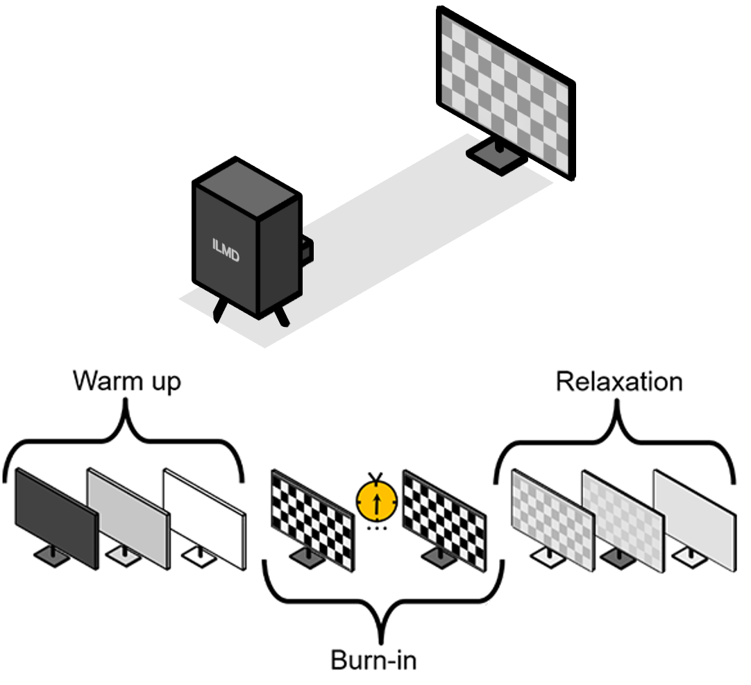
Top: General setup of an image sticking measurement using an Imaging Luminance Measurement Device (ILMD) as for instance the LMK6
Bottom: General schedule of an image sticking measurement series with exemplarily test patterns
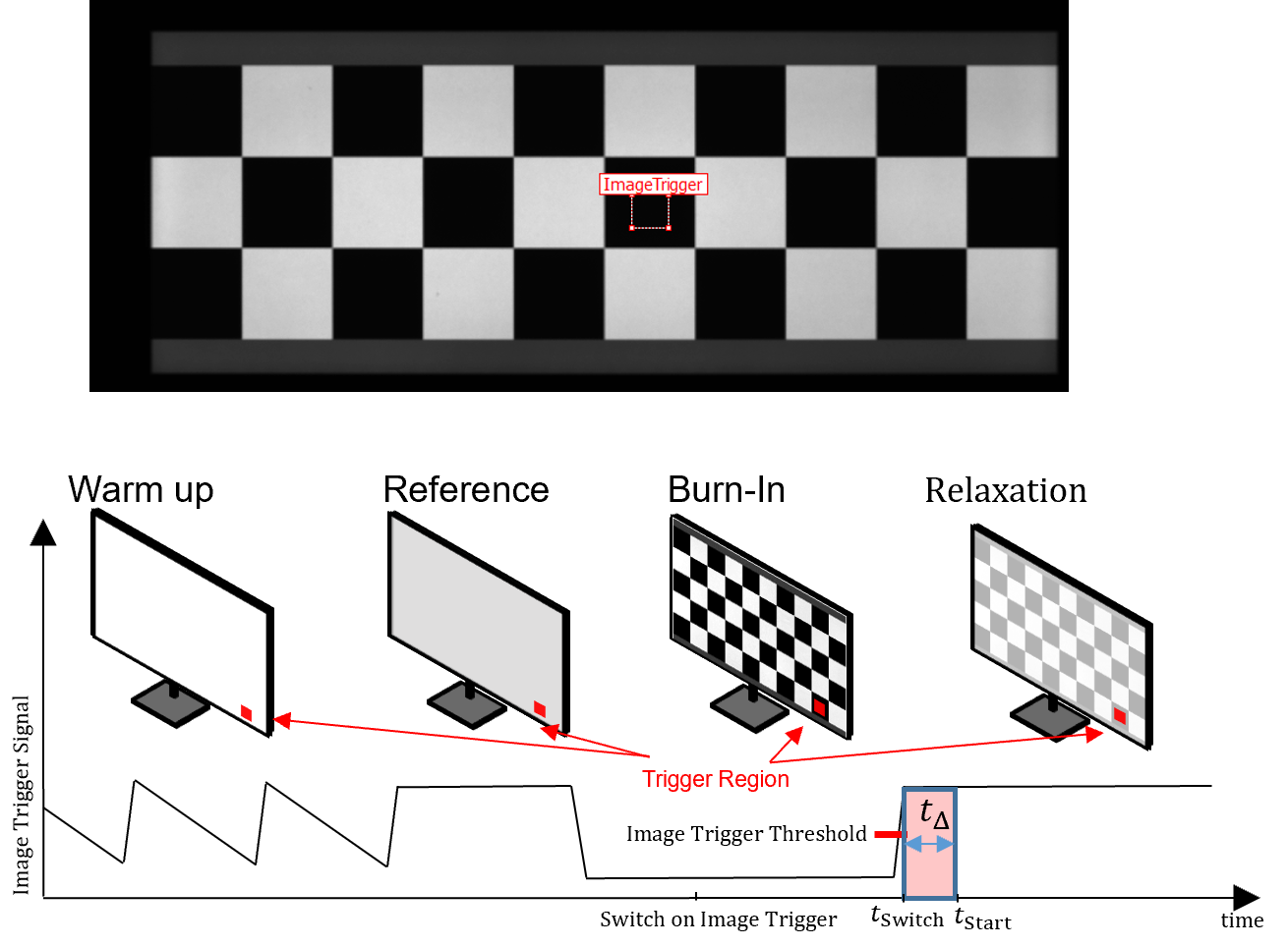
Top: User-Interface to select the trigger position
Bottom: Working principle of the trigger during an image sticking measurement
Impact of timing
The measurement start of the first relaxation image needs to be well-aligned with the pattern switching from the burn-in to the relaxation image to correctly assess the initial level of image sticking. If the measurement starts too late, the image sticking will already begin to vanish. If the measurement starts too early, and parts of the burn-in pattern are evaluated by accident, then the value will be too high. All this gets more complex in the context of setup and display-dependent input lags between sending the pattern switching signal and the actual pattern switching.
To overcome complex temporal alignment strategies, TechnoTeam developed an image content-based trigger for the LMK6. The camera will observe a freely adjustable part of the burn-in pattern with a very high frequency and optically detect the pattern switching.From this well-defined reference point, the measurement start can be set with any chosen delay, simply and reproducibly. The images on the right visualize the working principle of TechnoTeams image content-based trigger during an image sticking measurement. The image-content-based trigger method for image sticking is covered by TechnoTeam's international patent family — see US 11,557,111 B2.
Grey-level dependency and uniformity correction
In image sticking measurements, it is key to separate static display non-uniformity from non-uniformity caused by image sticking. There are two different ways to do this separation: The temporal and the local approach. Furthermore, static non-uniformity and the induced image sticking can strongly depend on the grey level, as the measurement example below shows.
TechnoTeam's software solutions offer total flexibility regarding the applied grey levels and the type of non-uniformity corrections with all their advantages and disadvantages — even in post-processing. That way, we can ensure that the image sticking measurement can be tailored to the specific project.
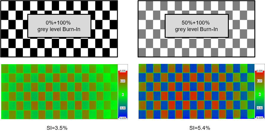
Example for the impact of the grey levels: For this liquid crystal test display, different burn-in and relaxation grey levels lead to significantly different image sticking results
Results
The image sticking results are given as time-resolved measurement values in percentages including all raw data. Also, all raw images can be saved during an image sticking measurement series. This also allows post-processing data, e.g., the change of the non-uniformity correction between the local and temporal approach. The 3-Level approach from the DFF further introduces a spatial aspect, where the image sticking phenomenon is analyzed for different columns. This concept also allows a direct extension to color-image sticking measurements, which is important for, e.g., OLED displays.
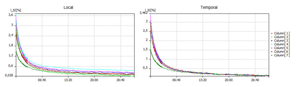
Image sticking relaxation results with two different types of non-uniformity correction: Left: Local and Right: Temporal. The type of correction can also be changed after the measurement for some methods
Summary
This Application Note introduced the temporal phenomenon of image sticking and what aspects should be considered during its measurement. Starting from the basic measurement principles, important measurement aspects were discussed briefly. Because an image sticking measurement takes so much time, the three aspects — temporal alignment, grey level dependency and non-uniformity correction — should be settled before the measurement starts, together by the measurement engineer and the person who owns the specification.
Download
References
| [1] | ICDM, "RESIDUAL IMAGE (10.4), in IDMS: Information Display Measurements Standard, (2012) |
| [2] | K.-H. Blankenbach et al., "Recent Standardization Efforts and Measurement Procedures of German Automotive OEM and German Flat Panel Forum (DFF)," SID Digest, pp. 361-364, 2016. |
| [3] | H.-U. Lauer, C. Beutel, J. Faber, G. Kammerer, "Extended analysis of Sticking Image by using a 3-level burn-in pattern", in SID-ME Chapter Fall Meeting, (2010). |
| [4] | H.-U. Lauer, C. Beutel, J. Faber, "extended analysis of sticking image by using a 3-level burn-in pattern", in electronic displays conference (2013). |
| [5] | J. Bauer, K. Blankenbach, "Proposal for a Standard Measurement Procedure and Objective Characterization of Imagesticking in TFT-LCDs in Reference to Display Quality and Customers Value Perception" SID-ME Chapter Fall Meeting (2010) |
| [6] | J. Kim, K. Choi, S. Jung, J. Langehennig, D. Lee, B. Min, "An Evaluation Methodology for Display Retention Measurement", in SID 2018 DIGEST, (2018). |
| [7] |
I. Rotscholl, U. Krüger, "Aspects of Image Sticking Evaluations Using Imaging Luminance Measurement Devices", in SID DIGEST 2019. |
| [8] | H.-U. Lauer et al., "Accurate measurement and inspection of sticking image in TFT LCDs," in SID Mid-Europe Chapter Fall Meeting, 2010 |
| [9] | I. Rotscholl, U. Krüger, "Non-uniformity correction in recent automotive image sticking evaluation methods" in SID Vehicle conference 2019. |
| [10] | D.-G. Lee, I.-H. Kim, H-S. Soh, B. C. Ann "Measurement and Analysis Method of Image Sticking in LCD", in SID 02 DIGEST, (2002). |
| [11] | I. Rotscholl, U. Krüger, "Requirements on the characterization of optical display attributes for automotive applications" in SID Vehicle conference 2018. |
| [12] | G. Steinaecker et al., "Image Sticking von LCDs," http://www.burosch.de/images/docs/ed_2005_image_sticking_LCD_final.pdf, 2018. |
| [13] | H.-J. Park et al., "Analysis of IPS Mura, Image Sticking and Flicker caused by Internal DC Effects,," in SID Digest, 2003. |
| [14] | K. Tsutsui et al., "An Image Sticking Free Novel Alignment Material for IPS-LCD," in SID Digest, 2003. |
| [15] | F. Wölzl, Degradation Mechanisms in Small Molecule Organic Electronic Devices, 2016. |
| [16] | K. Kam, T. Yu, K. Behrman, C. Yu, I. Kymissis, "Characterizing Image Retention for HDR OLED Displays" in SID DIGEST 2020 |